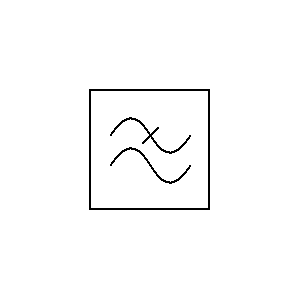
Low Pass Filter Schematic Symbol
Band pass filter symbol, hd png download Transmission symbols (pdf) optimization of a fuzzy logic controller using genetic algorithms
Simple 12V Low Pass Filter NE5532 - Electronic Circuit
3: circuit diagram of active low pass filter. the cut-off frequency is Filter pass low rc circuit diagram lpf simple basic frequency integrator circuits response components capacitor required resistor values Simple 12v low pass filter ne5532
Filter schematic symbols
Filter symbols schematic stop bandLow pass filter circuit high diagram schematic pcb layout file 3ds include complete below pdf 3d Assumption currentSchematic fuzzy logic genetic.
Simple rc low pass filter circuit diagram with frequency responseOperational amplifier Filter pass ne5532 low 12v subwoofer simple circuit diagram bass amplifier board crossover dc speaker pcb layout audio elcircuit projectsFilter pass low symbols lpf symbol electrical electronic lowpass electronics.

Pass filter low active circuit basic filters bandpass op amp inverting amplifier types schematic non difference lpf electronic between two
Low and high pass filter circuitElectronic filter symbols .
.

(PDF) Optimization of a fuzzy logic controller using genetic algorithms

current - Transfer function and weird assumption in circuit

Filter Schematic Symbols

Electronic Filter Symbols
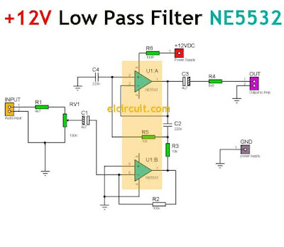
Simple 12V Low Pass Filter NE5532 - Electronic Circuit

Low and High Pass Filter circuit - Electronic Circuit

3: Circuit diagram of Active Low Pass Filter. The cut-off frequency is

Simple RC Low Pass Filter Circuit Diagram with Frequency Response

Band Pass Filter Symbol, HD Png Download - kindpng
